Se creará el driver para la lcd grafica 96x64 con interfaz de comunicación RSPI. Se mostrará un mensaje de 7 líneas.
- Crear y configurar la unidad RSPI0
- Inicializar los pines de LCD-CS y LCD-RS
- Incluimos todos los archivos de la librería gráfica en una carpeta
DESARROLLO:
- Del manual Renesas RX63N RDK User's Manual ubicamos los pines del LCD:


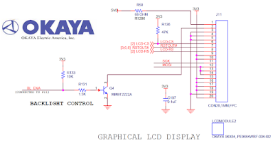
- Del YRDKRX63N schematic ubicamos el LCD okaya:

PASOS:
- Creación de un proyecto:
2.- New/ C Project / Renesas RXC ToolChain

3.- Seleccionar el target R5F563NB, debug hardware Segger jLink, después next

4.- Seleccionar la librería math.c para las funciones test de la LCD gráfica.

5.- Seleccionar C/C++ Source file y por ultimo Finish.

6.- Configuraremos el SPI por medio del módulo RSPI0 a 0.5 Mbps en el archivo r_cg_serial_SPI.c:
void R_RSPI0_Create(void)
{
//SYSTEM.PRCR.WORD = 0xA502; /* Protect
off */
MSTP(RSPI0)
= 0; //Enable SPI0
//SYSTEM.PRCR.WORD = 0xA500; /* Protect
on */
MPC.PC5PFS.BYTE = 0x0D; /* PC5 is RSPCKA */
MPC.PC6PFS.BYTE = 0x0D; /* PC6 is MOSIA */
MPC.PC7PFS.BYTE = 0x0D; /* PC7 is MISOA */
//PORT C DDR
PORTC.PDR.BIT.B5 = 1; //An output pin RSPCK output
PORTC.PDR.BIT.B6 = 1; //An output pin MOSI output
PORTC.PDR.BIT.B7 = 0; //An input pin MISO = input
PORTC.PMR.BIT.B5 = 1; // como periferico
PORTC.PMR.BIT.B6 = 1; // como periferico
PORTC.PMR.BIT.B7 = 1; // como periferico
// inicializa
pines
PORTC.PDR.BIT.B2 = 1; // como salida
LCD-CS
PORT5.PDR.BIT.B1 = 1; // como salida
LCD-RS
PORTC.PDR.BIT.B3 = 1; // como salida
reset
PORTC.PMR.BIT.B2 = 0; // como
I/O general
PORT5.PMR.BIT.B1 = 0; // como
I/O general
PORTC.PMR.BIT.B3 = 0; // como
I/O general
PORTC.PODR.BIT.B3 = 0; // Pull RSTOUT# inverting buffer low so
RSTOUT# goes high, releasing reset state.
//SPPCR register
RSPI0.SPPCR.BIT.SPLP = 0; //Disable loopback mode
RSPI0.SPPCR.BIT.SPLP2 = 0; //Disable loopback mode
//RSPI0.SPPCR.BIT.SPOM = 0; //CMOS
output
RSPI0.SPPCR.BIT.MOIFV = 0; //MOSI idle fixed value equal 0
RSPI0.SPPCR.BIT.MOIFE = 0; //MOSI output value equal final data
from previous transfer
/* Set RSPI bit rate (SPBR) */
/* -Set baud rate to 0.5 Mbps = 48MHz / (2 * (47 + 1) *
2^0) */
RSPI0.SPBR = 47;
//SPDCR register
RSPI0.SPDCR.BIT.SPFC = 0; //Number of frames
//RSPI0.SPDCR.BIT.SLSEL = 0; //SSL0 to
SSL3 as output
RSPI0.SPDCR.BIT.SPRDTD = 0; //SPDR values are read from the receive
buffer
RSPI0.SPDCR.BIT.SPLW = 0; //SPDR is accessed in words
//SPCKD register
RSPI0.SPCKD.BIT.SCKDL = 0; //1 RSPCK delay for clock
//SSLND register
RSPI0.SSLND.BIT.SLNDL = 0; //1 RSPCK delay for slave select
negation
//SPND register
RSPI0.SPND.BIT.SPNDL = 0; //1 RSPCK + 2 PCLK delay for next-access
//SPCR2 register
RSPI0.SPCR2.BIT.SPPE = 0; //Parity disable
RSPI0.SPCR2.BIT.SPOE = 0; //Parity mode
RSPI0.SPCR2.BIT.SPIIE = 0; //Disable idle interrupt
RSPI0.SPCR2.BIT.PTE = 0; //Disable the self-diagnostics of the
parity circuit
//SPCMOD0 register (Graphic display)
RSPI0.SPCMD0.BIT.CPHA = 0; //Data sampling on odd edge, data
variation on even edge
RSPI0.SPCMD0.BIT.CPOL = 0; //RSPCK = 0 when idle
RSPI0.SPCMD0.BIT.BRDV = 0; //Bit Rate = 3MHz (according with SPBR
register)
RSPI0.SPCMD0.BIT.SSLA = 0; //SSL3-A for graphic display
RSPI0.SPCMD0.BIT.SSLKP = 0; //Negative all SSL signals upon
completion of transfer
RSPI0.SPCMD0.BIT.SPB = 7; //Data length = 8bits
RSPI0.SPCMD0.BIT.LSBF = 0; //MSB first
RSPI0.SPCMD0.BIT.SPNDEN = 0; //Disable next-access delay
RSPI0.SPCMD0.BIT.SLNDEN = 0; //Disable SSL negation delay
RSPI0.SPCMD0.BIT.SCKDEN = 0; //An RSPCK delay of 1 RSPCK
//SPCR register
RSPI0.SPCR.BIT.SPMS = 1; //SPI operation (four-wire)
RSPI0.SPCR.BIT.TXMD = 0; //Full-duplex operation
RSPI0.SPCR.BIT.MODFEN = 0; //Disable detection of mode fault error
RSPI0.SPCR.BIT.MSTR = 1; //Master mode
RSPI0.SPCR.BIT.SPEIE = 0; //Disable error interrupt requests
RSPI0.SPCR.BIT.SPTIE = 1; //enable transmit interrupt requests
RSPI0.SPCR.BIT.SPRIE = 1; //enable receive interrupt requests
RSPI0.SPCR.BIT.SPE = 1; //Enable RSPI function
//SSLP register
RSPI0.SSLP.BIT.SSL0P = 1; //SSL0 signal is 1 active
RSPI0.SSLP.BIT.SSL1P = 1; //SSL1 signal is 1 active
RSPI0.SSLP.BIT.SSL2P = 1; //SSL2 signal is 1 active
RSPI0.SSLP.BIT.SSL3P = 1; //SSL3 signal is 1 active
//SPSCR register
RSPI0.SPSCR.BIT.SPSLN = 0; //RSPI
sequence
}
7.- Inicializamos la LCD con la función en main.c
void SR_LCD_GRAPH(void)
{
LCDInit();
LCDClear();
//LCDTest2();
LCDFont(FONT_LARGE);
}
8.- La función de envió se muestra a continuación y
está en el archivo r_cg_serial_SPI.c
MD_STATUS R_RSPI0_Send_Receive(uint8_t *
tx_buf, uint16_t tx_num, uint8_t *
rx_buf)
{
MD_STATUS status = MD_OK;
RSPI0.SPDR.WORD.H =
0x00ff & *tx_buf;
//Wait for transfer complete
while (RSPI0.SPSR.BIT.IDLNF)
{
__nop();
}
(void) RSPI0.SPDR.WORD.H ;
G_SPI_SendingData
= 0;
return (status);
}

- Agregar código, compilar y debug:
--.> Practica #4
2.- Compilar con el icono del martillo y debug con el icono del insecto:

DEMOSTRACIÓN:

No hay comentarios.:
Publicar un comentario